Electrical Analogy to Heat Transfer
You will need to refresh the browser for the equations to show
Objectives
- Represent Heat Transfer as a set of electrical circuits
- Solve an electrical circuit
- Represent an electrical circuit as a set of differential equations
If you can already complete the above tasks, continue to the challenge section at the bottom of the page
Thermal to Electrical Comparison
Thermal properties can be directly compared to electrical properties in a circuit. For the rest of this course we will be using the thermal equivalent.
Temperature - Voltage
Heat Transfer - Current
Thermal Resistance - Electrical Resistance (Inverse of Conductance)
Thermal Capacitance - Electrical Capacitance
Heat transfer representation
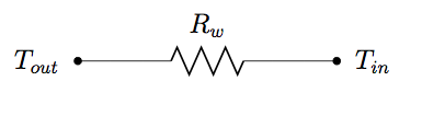
Calculation
The heat transfer through the above conductance can be calculated as
Q is the rate of heat transfer from T1 to T2
Drawing a Circuit
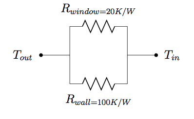
Let us assume that we have a house with the following properties
- Windows with a resistance of 0.2K/W
Walls with an overall resistance of 0.05 K/W
The equivalent circuit representation looks like this. The circuits are in parallel because the windows are physically in parallel with each other
If we were to add some additional insulation to the wall this would be represented with an additional resistor in series
Let's add some additional insulation to the wall which has a total resistance of 0.03 K/W
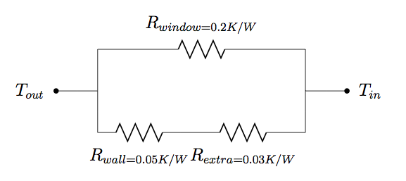
The resistor is added in series as the heat energy first passes through the wall, and then the added insulation.
Solving the Circuit
Resistances in series are added as so
Resistances in parallel are added like so:
Note: All series resistors must be added before parallel resistors can be added
Adding Capacitance
Many thermodynamic systems have a thermal capacitance. In a building, this is caused by the mass of the building holding in heat.
A capcitance is connected to one of the temperature nodes. This thermal node will then have some delay. Let's assume that the building in question has a thermal capacitance of 2000Wh/K
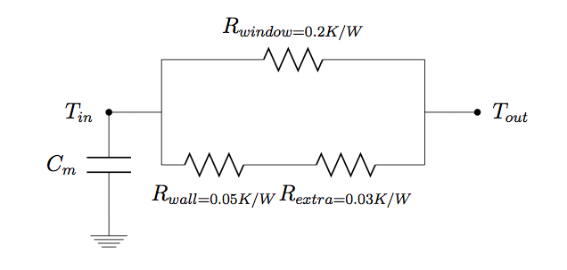
We can simplify the resistances as we did before to get
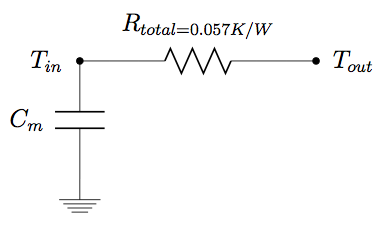
This is known as a 1R1C building circuit which we will use for our first computation model. Although it is simple, it has proven to be accurate enough for simple tasks See Paper Here
Solving
The equation for the heat disipating from the thermal mass is
Remembering from earlier for the resistor
If we think about the conservation of energy. All the heat leaving the thermal mass and entering the thermal node T_in must also leave the thermal node T_in through the resistor. This is also known as Kirchoffs Current Law
so
solving we get the differential equation
This video explains this for electrical circuits
In the next chapter we will use numerical methods to solve this
Test
1) Draw the electrical circuit analogy for a room with two windows and a wall. The room has an internal thermal capacitance.
2) Derive the differential equation for this circuit